UML Class Diagrams — The Basics
This page is a brief summary of the things you need to know to draw UML class diagrams. Think of it kind of like a cheat-sheet :)
A printer-friendly version can be found here. It fits on 1 piece of A4 paper with 2 pages per side.
Scott W. Ambler defines UML class diagrams quite clearly:
“UML class diagrams show the classes of a system, their interrelationships, and the operations and attributes of the classes. [..Class diagrams..] are used to:
- explore domain concepts in the form of a domain model.
- analyze requirements in the form of a conceptual/analysis model.
- depict the detailed design of object-oriented or object-based software.”
Classes
Section titled “Classes”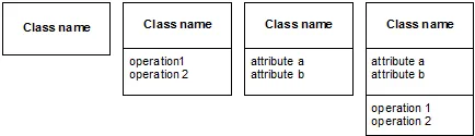
Classes are the central element in class diagrams. A class can have up to 3 compartments, for name, operations and attributes. It is only mandatory to show the name. If all 3 compartments are used, operations are shown in the bottom compartment and attributes are shown in the middle compartment. That is hard to remember, so I always append “()” to operations to distinguish them from attributes.
Attributes and operations
Section titled “Attributes and operations”The syntax for specifying attributes and operations is:
Attributes: visibility name : type multiplicity = default {property-string} – name : String [1] = “Anonymous” {readOnly}
Operations: visibility name (parameter-list) : return-type {property-string}
parameter-list: direction name : type = default-value + balanceOn (date : Date) : Money
The only mandatory part of the description of an attribute or operation is the name.
Example
Section titled “Example”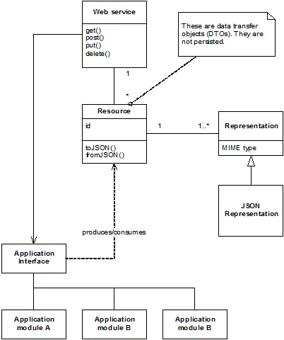
The above is an example class diagram. Classes are connected via associations. When classes are associated, they “know” each other or they are somehow related. In the software, it means that the web service and application interface knows each other, probably by one having a reference to the other. If I want to be specific and say that I can navigate from the web service to the application interface, I will add an arrowhead to the association, pointing from the web service to the application interface.
The application interface has a dependency relation to the resource class. This is shown as a dotted line with an arrowhead. In software this means that if the resource class changes, the application interface will probably be affected. This could be because the application interface has an operation that takes a resource as a parameter.
Multiplicities
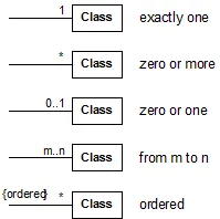
Section titled “Multiplicities”The association between the web service class and the resource class is annotated with multiplicities. The association reads: “One (1) web service is related to many (*) resources”.
The different multiplicities are:
Composition and aggregation
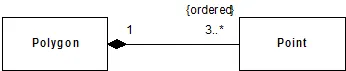
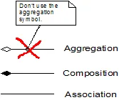
Section titled “Composition and aggregation”UML has symbols for aggregation and composition. Composition means that the lifecycle of one class is controlled by the other class. An example is the polygon, which has 3 or more points. The points belong to the polygon and an instance of the polygon class has instances of the point class. If the polygon instance is deleted, the point instances are also deleted.
Interfaces
Section titled “Interfaces”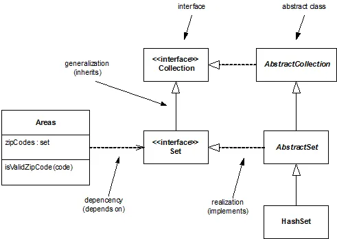
Interfaces can inherit from other interfaces, like classes can inherit from other classes. Classes can implement interfaces and then they are said to provide the interface. A class can also depend on an interface and then it is said to require the interface. This can also be shown in “ball-and-socket” notation:
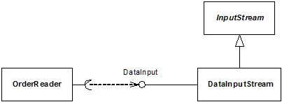
Here the DataInputStream class provides an interface and the OrderReader class requires the same interface. The notation with a dependency from the socket to the ball is correct UML, but often the ball and socket is shown together, because it is easier to draw (and looks better).
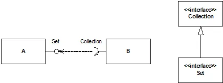
However, it sometimes still makes sense to use the dependency arrow. An example of this is where a class B, which requires a Collection interface can have its requirement fulfilled by class A, which provides a Set interface. This is valid, because the Set interface inherits from the Collection interface.