RPi Pico 2W — Using PWM
Pico 2 PWM overview can be found in the datasheet on page 1077.
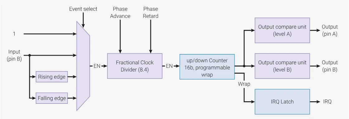 Illustration from the RP2350 datasheet
All GPIO can be configured to connect to PWM. The table on page 1078 in the datasheet has the details.
 Table from the RP2350 datasheet
There are 12 “slices”, which each drive 2 outputs: A and B. The PWM
period is controlled by the wrap value for a slice. This means that
output A and B for a slice will have the same wrap value. The duty cycle
is controlled by the level value for the outputs, which are separate
for A and B. This is illustrated in the following figure from the
datasheet, where “TOP” is the wrap value and “TOP/3” is the level value:
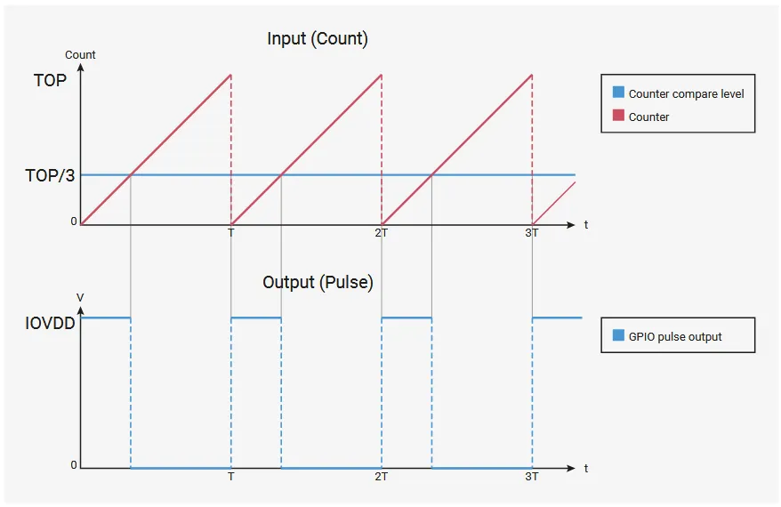 Illustration from the RP2350 datasheet
The PWM frequency will be the system clock divided by the value of the Fractional Clock Divider divided by the PWM period. The RP2350 system clock is 150 MHz.
First, add the hardware_pwm library to CMakeLists.txt for PWM
support.
target_link_libraries(my_project pico_stdlib hardware_pwm)Now the steps are:
- Configure GPIO pin(s) for PWM.
- Set the period and duty cycle.
- Configure the clock divider.
- Start and stop PWM using the
pwm_set_enabledfunction.
    gpio_set_function(8, GPIO_FUNC_PWM); // set GPIO 8 to PWM - this is connected to slice 4A    gpio_set_function(9, GPIO_FUNC_PWM); // set GPIO 9 to PWM - this is connected to slice 4B    uint8_t slice_num = pwm_gpio_to_slice_num(9); // find the 'slice' to configure
    // Set period of 99 cycles (0 to 99 inclusive)    pwm_set_wrap(slice_num, 99);
    // Set channel A output high for 10 cycles before dropping    pwm_set_chan_level(slice_num, PWM_CHAN_A, 9);
    // Set initial B output high for 50 cycles before dropping    pwm_set_chan_level(slice_num, PWM_CHAN_B, 49);
    // divide the system clock (150MHz) with 150    pwm_set_clkdiv(slice_num, 150.f);
    // Set the PWM running    pwm_set_enabled(slice_num, true);
The level controlling the duty cycle can be set by the
pwm_set_gpio_level(uint gpio, uint16_t level) function. If set to 0,
the output is always low; if set to wrap + 1, the output is always
high.
Exercise
Section titled “Exercise”- Add functions to increase and decrease the duty cycle.
- Make sure to limit the
levelto be between 0 andwrap+ 1. - Call the increase and decrease functions from a UART interrupt, to make it possible to control the duty cycle from a terminal.
- Measure with an oscilloscope.